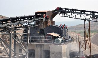
Schematic Diagrams For Dry Ball Milling Circuits

AMIT 135: Lesson 7 Ball Mills Circuits – Mining Mill ...
Wet Ball Mill = kg kWh = (A ) ; Dry Ball Mill = kg / kWh = i ; Replacement Ball Size. Rowland and Kjos proposed the use of their equation for the determination of the initial and replacement media size. Azzaroni (1981) and Dunn (1989) recommended the use of the following expression for the size of the makeup media:
PARTS LISTINGS WIRING DIAGRAMS for the HURCO Autobend .
All five (5) sections also contain electromechanical assemblies and wiring diagrams that are intended as an aid in isolating a malfunction when it becomes necessary to troubleshoot the machine to find the source of an encountered p roblem. Always flexing the printed circuit boards (PCBs, also called printed wiring boards or PWBs) when handling, removing, or inserting them. NOTICE Hurco ...
Back to Basics Hammer Milling and Jet Milling Fundamentals
In dry milling appliions, a highmoisture feed material can flow poorly and build up on the grinding chamber wall, classifier wheel, and conveying line. This can reduce mill capacity and air classifier performance. Particle surface chemistry can affect many material properties that affect flow, including stickiness, affinity for water, and tendency to accumulate electrostatic charge. The ...
Schematic Diagrams For Dry Ball Milling Circuits
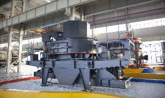
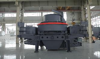
schematic diagrams for dry ball mill peru costing circuits. Ball mill, A ball mill is a type of grinder used to grind or blend materials for use in mineral dressing The ball mill can grind ores and other materials, wet or dry. Ball milling boasts several advantages over other systems: the cost of installation operation; it is suitable for open ...
Typical Electrical Drawing Symbols and Conventions.
Basics 6 kV 3Line Diagram : Basics 7 kV 3Line Diagram : Basics 8 AOV Elementary Block Diagram : Basics 9 kV Pump Schematic : Basics 10 480 V Pump Schematic : Basics 11 MOV Schematic (with Block included) Basics 12 12/208 VAC Panel Diagram : Basics 13 Valve Limit Switch Legend : Basics 14 AOV Schematic (with Block included)
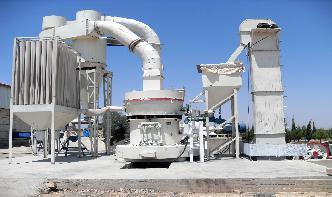
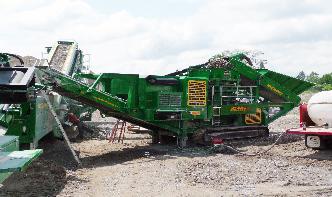
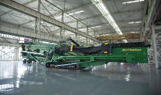
Dry Milling
Dry milling (Fig. ) involves grinding the incoming grain, then processing it through a series of steps to liquefy the flour and generate fermentable are added at two points in the process—the initial slurry step, and the liquefaction step, which follows a jet cooking operation that uses hightemperature steam to swell the starch.
schematic diagrams for dry ball milling circuits
Diagram Of A Ball Mill Circuit. Schematic diagrams for dry ball milling circuits effects of ball milling and sintering on alumina and effects of ball milling and sintering on alumina and aluminaboron compounds thomas cross pellets are dry pressed from the milled powders sintered at 1200c for one to 10 hours and characterized to determine the impact of processing .
ENGINEERING SYMBOLOGY, PRINTS, AND DRAWINGS Module 2 ...
Module 2: Engineering Fluid Diagrams and Prints Page 1 ENGINEERING FLUIDS DIAGRAMS AND PRINTS To read and understand engineering fluid diagrams and prints, usually referred to as PIDs, an individual must be familiar with the basic symbols. EO IDENTIFY the symbols used on engineering PIDs for the following types of valves: a. Globe valve g.
Pneumatic Schematics and Basic Circuit Design 352
Basic Pneumatic Schematics and Circuit Design provides an overview of different common pneumatic schematic symbols, including air treatment symbols; pressure, flow, and direction valve symbols; and actuator symbols. Further, the class describes an overview of the design principles of a pneumatic circuit and the placement of components within a pneumatic schematic.
How to Build a Printed Circuit Board
Advanced Circuits Inc 2004 26 Outer Layer Expose Develop After dry film lamination the panel is exposed and developed using the same procedure used for the inner layer cores. Clear areas in the film allow light to pass through and harden the resist creating an image of the circuit pattern All
Cnc Endstop Wiring Diagram
· Go to the new parallel breakout board to get more information and the wiring diagram. Switch wiring. Eagle light schematic: File:Mechanical endstop wiring When the switch is off (like in the schematic above), it connects signal to ground. When the switch is triggered, the ground connection is cut and the signal is connected to 5v through the pull up resistor. Feb 13, · The ...
Electrical Symbols and Line Diagrams
electrical circuit. Oneline diagrams are used when information about a circuit is required but detail of the actual wire connections and operation of the circuit are not. 2 Line Diagrams A line (ladder) diagram is a diagram that shows the logic of an electrical circuit or system using standard symbols. A line diagram is used to show the relationship between circuits and their components but ...
Best Electronic Circuit Projects
POWER SUPPLY CIRCUITS: Fixed type and variable voltage and current power supply circuits are given here... best circuit projects suited for workbench testing. AMPLIFIER PROJECTS: Projects to amplify small music inputs from ipod, cellphone or an SD card to get 100s of watts on loudspeaker. Boom your surrounding with the help of these projects.
schematic diagrams for dry ball milling circuits,
Ball Mills Schematic Diagram Of Ballmill Crusher Mills . schematic diagram of ball mill pdf in Cebu, Philippines Sep 22, 2012 nbsp ball mill schematic diagram manual pdf in Cebu, Philippines Find the Right and the Top schematic diagrams for dry ball milling circuits for your . More
Papermaking OVERVIEW AND INTRODUCTION 1. Introduction .
In this step, pulps are repulped (if delivered to the mill in dry form), refined, and blended to give the desired furnish for the particular grade of paper. This blended stock is then pumped to the machine chest. From here it is pumped as thick stock through a tickle refiner, stuff box, and lastly the basis weight valve which controls the fibre
Powder metallurgy – basics appliions
In dry milling, about 25 vol% of powder is added along with about 1 wt% of a lubricant such as stearic or oleic acid. For wet milling, 3040 vol% of powder with 1 wt% of dispersing agent such as water, alcohol or hexane is employed. • Optimum diameter of the mill for grinding powders is about 250 mm Ball Mill. R. Ganesh Narayanan, IITG Vibratory ball mill • Finer powder particles need ...
Understanding Basic Electronics is Easy
· Schematic Diagrams. To make any electronic circuit, you start with a schematic diagram. A schematic is a drawing of a circuit. It tells you which components are needed and how to connect these components. You can either design your own schematics or find free schematics available online. Designing schematics. There are some basic electronics theory you should know .
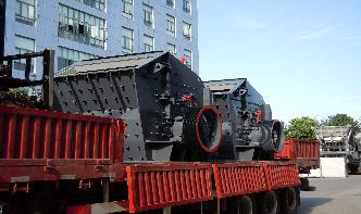
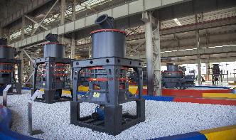
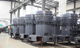
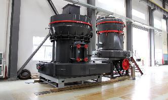
Ball Mill
18/11/2008 · Cost Ball mills, Ball charge are 31S/ton Cost Ball mills dry grinding 6 12. Cost Ball mills for wet grinding • To get the price of the ball mill for 2007: 7 13. Summary The Ball Mill is designed to grind materials by turning the cylindrical shell with grinding medium ( steel balls) put in the shell, and has a simple ...
How to Read Circuit Diagrams for Beginners
17/07/2017 · Circuit diagrams or schematic diagrams show electrical connections of wires or conductors by using a node as shown in the image below. A node is simply a filled circle or dot. When three or more lines touch each other or cross each other and a node is placed at the intersection, this represents the lines or wires being electrically connected at ...